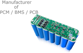


Battery Management Systm (BMS) with Communication protocol for 13, 16 cells in series Li-ion/Li-Polymer/LiFePO4 Battery Energy Storage System
Features and Benefits
Functional characteristics

Electrical performance parameters

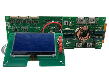
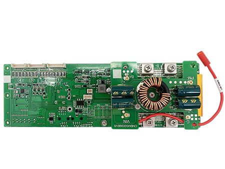
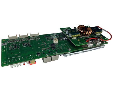
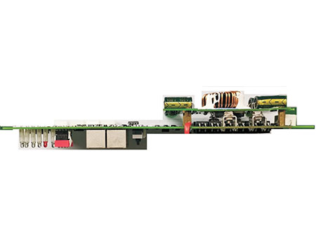
Product function diagram

Product function diagram

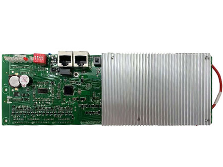
Specifications
Product Basic Function
1. Non-latching switch for reset 7. Charge overcurrent protection function
2. External weak current switch function 8. Discharge overcurrent protection function
3. System total voltage overcharge protection function 9. Short circuit protection function
4. System total voltage over-discharge protection function 10. Cell temperature protection function
5. Cell overvoltage protection function 11. Power tube temperature protection function
6. Cell over-discharge protection function
Product specific functions
1. Charge balance function 6. Charging current limiting function (optional function)
2. Sleep function 7. Charging mode
3. Wake up function 8. Battery heating function (optional function, default none)
4. SOC Accuracy and Calibration Function 9. Fault Detection Description
5. Pre-charge function (optional function, it is available by default) 10. Description of BMS charge and discharge minimum identification current

Connection Diagram


Communication function after multiple battery packs are connected in parallel
Parallel operation and setting steps of battery packs
•1 Turn off all battery packs, and connect the output positive and negative poles of all battery packs in parallel;
•2 Connected in sequence via standard RS485 network cable(see picture above)
•3 Set the PACK address in turn according to the picture below, and turn on all BMS in turn
•4 View the BMS data of the corresponding address through the PC Utility software or in accordance with the communication protocol.
•5 The battery pack BMS has a four-digit address dial switch, which is numbered according to the address from 0 to 15.
The battery pack BMS should detect the address of the dialer in real time, and the address of the dialer should be in binary mode

Single BMS mode
•In single BMS mode, the dip switch must be 0000, and the BMS works independently
Multi-slave parallel communication mode
•After the BMS is connected in parallel through RS485 communication, all BMSs are defaulted as slaves,
and the external Master system uses the RS485 bus to query all BMS data based on the system address of each slave.
The external Master system collects and aggregates all data (need an external Master system).
Multi-slave parallel communication mode
Almost all parameters can be logically programmed according to your cells’ specs on BesTech Software (Supports Windows System only), please be noted the
programming setting function is not open for everyone, the software normally is set as display for parameters only, BesTech Power only gives the access for
programming to customers who really understand BMS/Battery well.
With watchdog embedded in BesTech Software, the system is more robust, Battery Pack parameters are real-time displaying on our PC software/Bluetooth APP,
the data detection frequency is every 400mS. Any alarm/fault conditions are saved to our EEPROM (Please be noted the special conditions records will be lost if
BMS is resetor lost power).
To run BesTech Software, BesTech Programming Tool is needed (need purchase separately), the tool drive can be download from here. Our programming tool
is as below.

After communicating with the PC Utility software through RS485, you can obtain real-time battery voltage, current, temperature, SOC, system fault status and
other information; support system threshold parameter import and export
BesTech Software PC Utility (Windows only) downloading addressis here. Your windows system probably need another firmware to run smoothly, please
download from here.
Here is the screenshot for BesTech Software PC utility.
