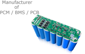


BMS With I2C, SMBus Communication protocol for Li-ion/Li-Polymer/LiFePO4 5S-10S Battery Pack
Features and Benefits
Programmable BMS with SMBus, I2C Communication protocol
1.Battery Management circuit board with SMBus for 5S~15S 80A Li-ion/Li-polymer and LiFePO4 battery pack;
2.BMS/PCB/PCM applies for 8S/9S/10S/11S/12S/13S/14S/15S/16S cells Li-ion/Li-polymer and LiFePO4 battery pack;
3.To prevent the battery packs from overcharge,overdischarge,over current, over temperature ,short circuit ;
4.The Maximal working current: 80A;
5.Compatible with both Li-ion/Li-polymer and LiFePO4 cells.
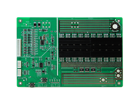
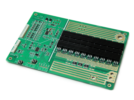
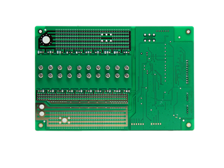
HCX-D298v1 BMS mainly designed based on TI chips, TIBQ78350+BQ76940/BQ76930/BQ76940, and the mosfets for discharge and charge current we mainly use IRF4310/IRF3207/IRF1404 (Only for reference), the specified parameters as below (all the logical parameters are adjustable from software).
(Note: the pictures or parameters in this data sheet are only for your reference, those possibly could be different from the ones you will order. Due to the upgrading of the Hardware/Firmware/Software, Characteristics subject to change without notice, for more information, please contact our technical engineers by email: info@bestechpower.com
Specifications
|
Item |
Contents |
Criteria (Adjustable from software/hardware) |
|
|
1 |
Model |
HCX-D298V1 |
5S-10S Adjustable from software and hardware |
|
2 |
Voltage |
Charging voltage |
Adjustable from software |
|
3 |
Current |
Maximal continuous charging current |
80A (adjustable from hardware) |
|
Maximal continuous discharging current |
80A (adjustable from hardware) |
||
|
Current consumption |
≤200μA
|
||
|
4 |
Overcharge Protection |
Over charge detection voltage |
Adjustable from software |
|
Over charge detection delay time |
Adjustable from software |
||
|
Over charge release voltage |
Adjustable from software |
||
|
5 |
Over Discharge Protection |
Over discharge detection voltage |
Adjustable from software |
|
Over discharge detection delay time |
Adjustable from software |
||
|
Over discharge release voltage |
Adjustable from software |
||
|
6 |
Over Current Protection |
Over current detection voltage |
Adjustable from software |
|
Over current detection current |
Adjustable from software and hardware |
||
|
Detection delay time |
Adjustable from software |
||
|
Release condition |
Adjustable from software |
||
|
7 |
Short Circuit Protection |
Detection condition |
Adjustable from software |
|
Detection delay time |
Adjustable from software |
||
|
Release condition |
Cut load, automatically recover |
||
|
8 |
Balance On @ ≥50mV±5mV OFF @ ≤30mV±5mV |
Balance voltage for single cell |
Adjustable from software |
|
Balance current for single cell |
Adjustable from hardware |
||
|
9 |
Resistance |
Inner resistance |
≤20mΩ |
|
10 |
Temperature |
Single cell temperature when discharge (over temp. protection) ≥65锟斤拷 |
Adjustable from software |
|
Single cell temperature when discharge (low temp. protection) <-40锟斤拷 |
Adjustable from software |
||
|
Single cell temperature when Charge (over temp. protection) ≥50锟斤拷 |
Adjustable from software |
||
|
Single cell temperature when Charge (low temp. protection) <0锟斤拷 |
Adjustable from software |
||
|
11 |
Fuel/Gas gauge |
Display with LEDs (optional) |
Thru one button to check capacity |
Connection Diagram
HCX-D298V1 Electrical Block Diagram ( Port 2, charge and discharge at the same port)
How to connect BMS to PC/laptop to set up all parameters and the communications.
The commnuication conventor tool is called “EV2300/EV2400” which can be purchased from BesTech or from TI.
BMS comes with
· BesTech Power BMS Software
· Specification of the communication conventeor tool
· BMS Specifications
· Battery Connection diagram
· BesTech Power Company profile
NOTE: this LED port on BMS are for extra fuel/gas gauge optional LED display.
After installed our software to your PC/laptop
The PC-end-software (copyright belongs to TI) to Set and modifying all the logical parameters
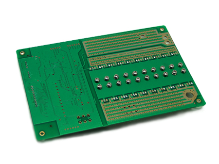
PCB Layout and size
Connections Diagram:
1) Charge and Discharge at the same port connection:
2) Charge and Discharge from different port connection:
Note:
Please connect B- of BMS to battery pack negative terminal then connect P+ to battery pack positive terminal, for the voltage detection cables, please connect from cell #1 till the last cell.
For more information, please email us at info@BesTechPower.com or sales@BesTechPower.com .
Thank you again for choosing BesTech Power.