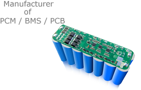


Battery Management system BMS,6S-20S with SMBus,UART, RS485, CANBus communication protocol for Li-ion/Li-Polymer/LiFePO4 Battery Packs
Features and Benefits
Programmable BMS with SMBUS, UART, RS485, CANBus Communication protocol
Specifications
|
Item |
Contents |
Criteria (Adjustable from software/hardware) |
|
|
1 |
Model |
HCX-D338 |
6S-20S Adjustable from software |
|
2 |
Voltage |
Charging voltage |
Adjustable from software |
|
3 |
Current |
Maximal continuous charging current |
80A (adjustable from hardware) |
|
Maximal continuous discharging current |
80A (adjustable from hardware) |
||
|
Current consumption |
≤200μA
|
||
|
4 |
Overcharge Protection |
Over charge detection voltage |
Adjustable from software |
|
Over charge detection delay time |
Adjustable from software |
||
|
Over charge release voltage |
Adjustable from software |
||
|
5 |
Over Discharge Protection |
Over discharge detection voltage |
Adjustable from software |
|
Over discharge detection delay time |
Adjustable from software |
||
|
Over discharge release voltage |
Adjustable from software |
||
|
6 |
Over Current Protection |
Over current detection voltage |
Adjustable from software |
|
Over current detection current |
Adjustable from software and hardware |
||
|
Detection delay time |
Adjustable from software |
||
|
Release condition |
Adjustable from software |
||
|
7 |
Short Circuit Protection |
Detection condition |
Adjustable from software |
|
Detection delay time |
Adjustable from software |
||
|
Release condition |
Cut load, automatically recover |
||
|
8 |
Balance On @ ≥50mV±5mV OFF @ ≤30mV±5mV |
Balance voltage for single cell |
Adjustable from software |
|
Balance current for single cell |
Adjustable from hardware |
||
|
9 |
Resistance |
Inner resistance |
≤20mΩ |
|
10 |
Temperature |
Single cell temperature when discharge (over temp. protection) ≥65℃ |
Adjustable from software |
|
Single cell temperature when discharge (low temp. protection) <-40℃ |
Adjustable from software |
||
|
Single cell temperature when Charge (over temp. protection) ≥50℃ |
Adjustable from software |
||
|
Single cell temperature when Charge (low temp. protection) <0℃ |
Adjustable from software |
||
|
11 |
Fuel/Gas gauge |
Display with LEDs |
Thru one button to check capacity |
Connection Diagram
Self-consumption in different working modes:
· Normal Operating Mode: 13mA typical, 18mA maximum self-consumption.
· Sleep Mode: 200μA typical, 300μA maximum self-consumption.
· The system automatically back to normal operating mode from sleeping mode if current is <2A after no communication signal for 60mins.
· The system also will be back from sleep mode to normal operating mode if any charge or discharge activity is detected or if there’s communication signal again
Voltage protection
· As soon as one cell’s voltage exceeds the protection point, the charging process will be interrupted on the whole pack. The protection circuit returns to normal conditions as soon as all the cell’s voltage falls back to normal. Thedischarge will be allowed and the cell balancing will be activated.
· As soon as one cell’s voltage is under the protection point, the discharging process will be interrupted on the whole pack, BMS will be in energy-saving mode, The protection circuit returns to normal operation mode as soon as all the cell’s voltage charged back to normal. When BMS protected up on discharging, the charging processing is still allowed.
Current protection
· Software:
>>As soon as the discharging current exceeds the over current detection current during the detection delay time, the discharging process will be interrupted. The BMS returns to normal conditions after over current detection current released.
· Hardware:
>>As soon as the discharging current exceeds the over current detection current during the detection delay time, the discharging process will be interrupted. The BMS returns to normal conditions after over current detection current released.
ESD:
Battery is protected against electrical discharges:
- 15kV air
- 8kV contact
LED indicator
Enter sleep mode
SM SU send command data to SM
How to connect BMS to PC/laptop to set up all parameters and the communications.
The communication conventor is an optional product which will not come with products normaly.
For engineering study, please send us email for this tool, then we will send you this together with our software drive coming with a USB drive as below:
(the communication convertor costs extra if needed)
· BesTech Power Software for BMS communication inside
· Specification of the Communication Conventeor inside
· BMS Specification inside
· Battery Connection diagram inside
· BesTech Power Company profile inside
After installed our software to your PC/laptop,
LED Fuel/Gas gauge display:
Battery cells connection instructions:
Commnucation ports connections:
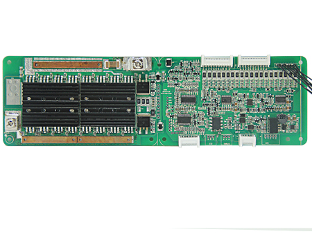
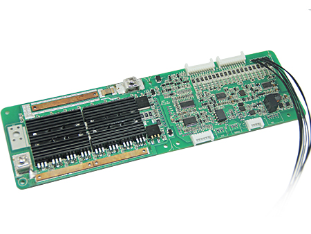
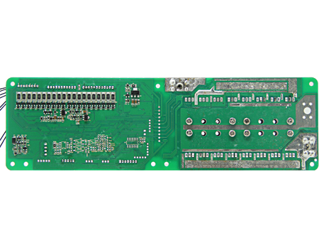
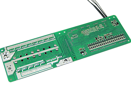
PCB Layout and size
For more information, please email us at info@BesTechPower.com or sales@BesTechPower.com .
Thank you again for choosing BesTech Power.